
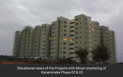
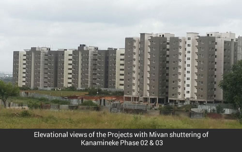
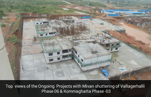
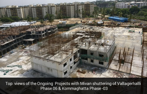
With a growing focus on affordable homes and Housing for All, Increasingly emphasizing on the use of new and innovative construction techniques. One such technology is Mivan shuttering which is being promoted for its ability to aid mass construction activity.
Its use is being promoted in India to realize the most ambitious government scheme – Housing for All by 2022.
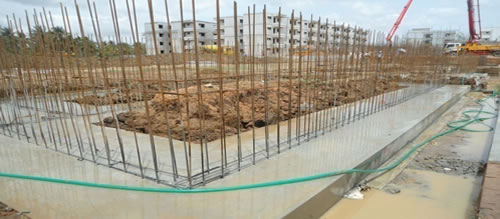
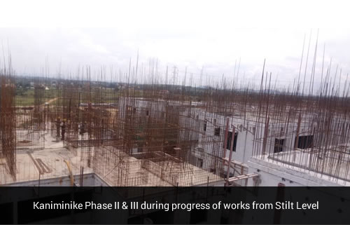
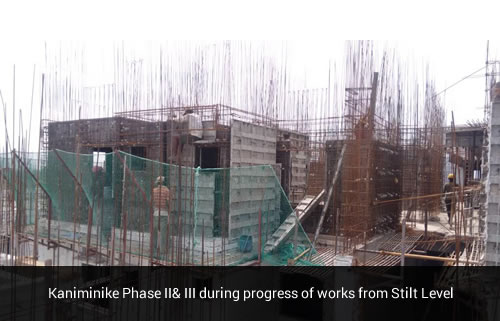
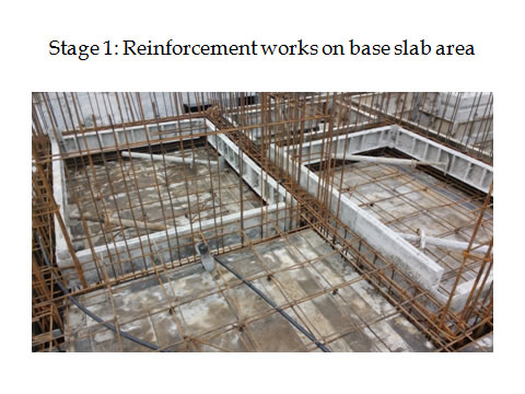
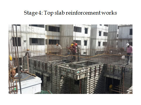
Setting up the wall Reinforcement steel – The wall reinforcing with steel is used to give a structure to the building and support the concrete until they gain half of the required strength. The aluminum formworks are cast around the steel mesh, which is factory made and directly erected on the construction site.
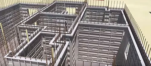
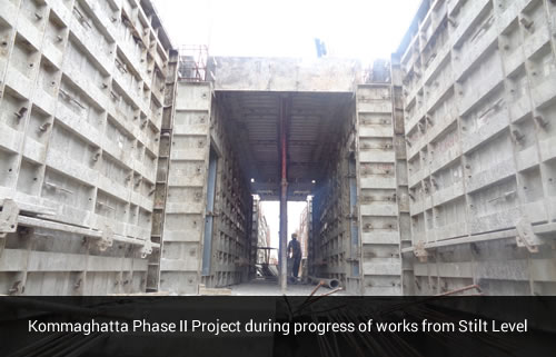
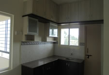
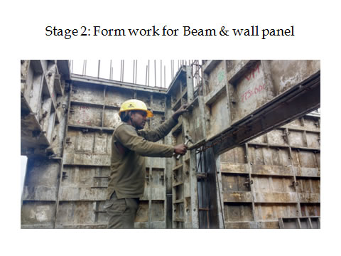
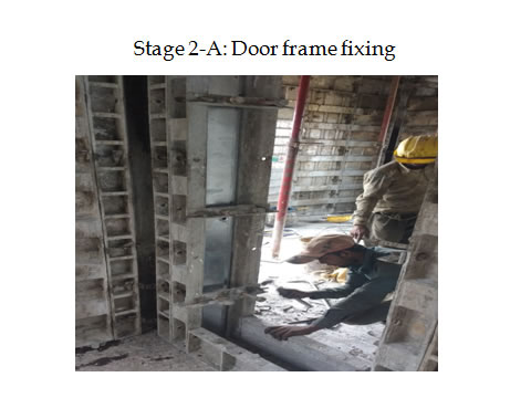
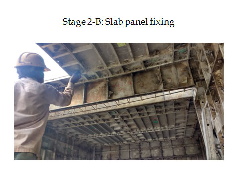
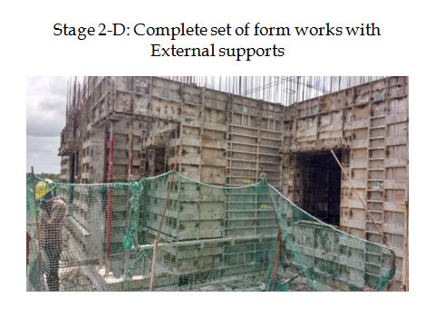
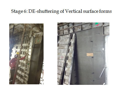
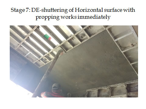
Placement of Aluminum formwork – Along the wall reinforcing steel, prefabricated room sized walls and floor slabs are erected. These aluminum alloy slabs are accurately made and are easy to handle. Spaces for windows, ducts, doors and other features such as staircases, façade panels, Lofts slabs (Kitchen counter slab with supporting walls) and chajjas are also integrated in these structures. The forms are joint together using the pin and wedge system, which can be dismantled quickly after the concrete structure is made for vertical surfaces and even for horizontal surface with immediately propping systems.
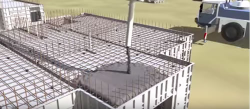
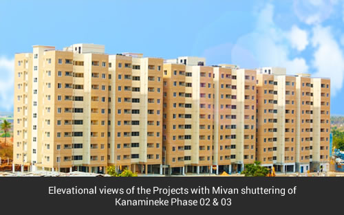
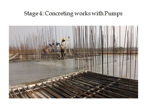
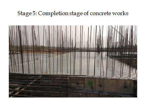
Pouring of concrete – After casting the forms, high-quality concrete is poured such as SCC type concrete with good and acceptable flow rates specially designed with rich mix. This concrete takes the form and shape of the cast reaching nuke and corners of the form works easy , which is later removed to make way for a structure made entirely of cement concrete supported by wall reinforcing members. The aluminum forms can be reused at least 250 times, resulting in minimum waste from the construction site.
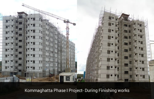
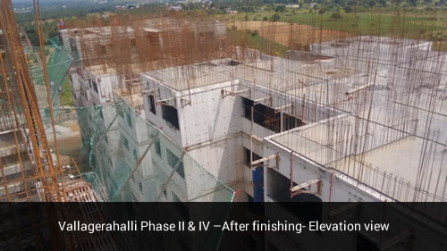
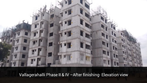
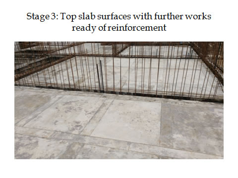
The resulting structure is accurate, smooth and finished. It has high tolerance and requires no further plastering. As a result, it saves time, effort and money.
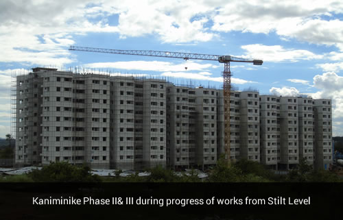
Mivan Technology reduces the construction time by almost half in comparison to conventional practices. Since it has a set procedure to be followed accurately, it minimizes the need for skilled labour and completely eliminates labour intensive activities such as masonry and rendering."
On the structural front, the technology makes the buildings more seismic-resistant and durable. Since there are lesser number of joints, the building faces reduced leakages, hence requiring negligible maintenance.
There is uniformity in Mivan construction and the walls and slabs have a smooth finish. Moreover, the technology gives the scope to take out more carpet area in comparison to conventional techniques.
| Sl No. | Stages of works | Days |
|---|---|---|
| 1 | Marking of surface for Form Panels placing and Reinforcement works | 01st day |
| 2 | Vertical reinforcement works | 02nd day |
| 3 | Vertical and Horizontal Form works Placing and Fixing in position with all accessories | 03rd Day |
| 4 | Concreting works for the complete units including Walls, Chejja , Lofts and Top Slabs including the sunken portions | 04th day |
| 5 | Wall Panel de-shuttering works after minimum 16 hours of continues curing and check on cube strength | 05th day |
| 6 | Slab Panels de-shuttering works after a period of 36 hours/ 3 days of concrete time of completion with immediate re-propping the slabs with continuous curing methods/ Curing compounds on surface application. | 06th day |
| Continuous curing will be carried out for 28 days as per standards, As these above days are for 1 Pouring unit of a house complete, same system will be continued in vertical and horizontal directions depending on the speedy of works systems. |
About Alternative technology for construction (Monolithic construction using Aluminium shuttering:
These houses are intended to be constructed in multiples of 2 houses / day on an average using Cast-in-situ concrete for all structural elements with aluminium "Wall Ties and Forms" (WTF) shuttering system. This procedure is adopted as one of the "Fast Track Construction Techniques", resulting in reduced cycle time, better quality control at site, less material mobilization and minimum labor involvement.In this methodology walls, lintel, beam, slab, chejja& kitchen platform are cast monolithically
As height of the building exceeds 15.0m, 2.0 hours fire rating is considered in the analysis and design of proposed structure.
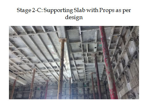
The Shuttering system is precisely-engineered system fabricated using aluminum conforming to architectural and structural requirements. Wall forms are used for wall shuttering connected through wall ties and clamps. Slab forms are used to support slabs for concreting. Slab forms are supported on props at appropriate location based on structural requirements, easy deshutteringsequence and handling of materials. Aluminium being lighter, shuttering material is easy to handle and place in position. The resulting structure has a good quality surface finish and accurate dimensional tolerances.
Wall forms are placed after the wall rebarfabrication, electrical conduting/ PHE conduting are complete. Wall forms are connected through the wall ties and clamps. Then slab forms are erected and required rebar fabrication, electrical conditingin slab will be carried out. Now, the unit is ready for concreting in one pour.
Self compacting concrete (SCC) of suitable grade as per mix design and structural requirements will be used for concreting. The inherent property of SCC is self compaction without segregation. Hence, SCC is more suitable for this technology. Free flow of concrete is maintained to be 600mm minimum,during the pour, to ensure the proper flow and compaction.
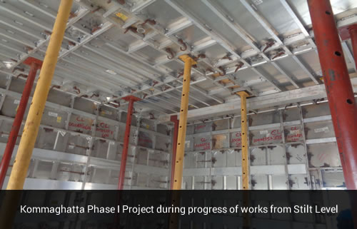
Deshutteringof wall forms will be carried out after 16-24 hours of concreting as per structural requirements. Slab forms will be removed after 3 days and props will be refixed at appropriate locations immediately after removal of slab forms
Curing is the process of controlling the rate and extent of moisture loss from concrete during cement hydration. Curing is designed primarily to keep the concrete moist, by preventing the loss of moisture from the concrete during the period in which it is gaining strength. Curing has a major influence on the properties of hardenedconcrete such as durability, strength, water-tightness, wear resistance, volume stability, and resistance tofreezing and thawing.
Membranes forming curing compounds (BASF Mastercure-107) are the liquids which are applied directly onto the concrete surfaces and which then dry to form a relatively impermeable membrane that retards the loss of moisture from the concrete immediately after removal of wall shuttering. This compound is wax based.
Slab are cured by ponding method for a minimum of 7 days
Conventional type of foundation such as wall strip foundation/Raft foundation based soil conditions will be used.
This type of construction is adopted due to the following advantages;
Keeping in view the above advantages with the alternate technology, this construction technology is more suitable for this project.
RCC is the primary material used in this construction. In conventional methods, RCC walls are cast first and slab is cast later. But, in this technology both walls and slabs are cast simultaneously. Walls are designed as shear walls using limit state method as per the standard design equations given in IS13920 and IS 456. Slabs are being designed as per IS 456. Element thickness (Walls, slabs and beams) are chosen based on fire rating and structural requirements. Limit state of strength is used for the structural design of various elements of the housing units. Limit state of serviceability (Stability, Cracking and Deflection) will be followed to ascertain durability criteria.
RCC is intended to be used in the proposed project. Guidelines conforming to IS 456, IS13920, IS 1893, IS 875 are followed to design the structure. Concrete (Portland cement + 30% (maximum) GGBS) and concreting procedures will be followed as per the Indian standard guidelines and practices. GGBS/Flyash reduces the micro cracks and protect the rebar thus increases the durability of concrete. Thus the structure built will be sound enough to be used as habitat building.
NISA/CIVIL (Numerically Integrated Elements for System Analysis) developed by M/s Cranes software International or ETABS will be used to analyse and design the propsed structure.
Best Indian practices would be followed during Planning, design and construction stages
The orientation of the building will be worked out based the energy conservation (Solar heat and light), without disturbing the existing site features
Site selection and planning requires connectivity to infrastructure and public transport network. The proposed site is well connected to public transport network.
Rain water harvesting is envisaged thus meeting the requirements of during scarcity days and recharging the source of water.
Dual piping system for treated water (Recycled water) and potable water will be adopted by using efficient plumbing fixtures.
Water Usage: As curing compounds are used, usage of water for curing is minimized during the time of construction.
Solar passive building design concept will be followed in order to reduce or even eliminate the use of mechanical cooling and heating systems and the use of daytime artificial lighting.
These parameters may be ensured with proper planning of building, its orientation, and location of windows, doors and window shades.
List of generally applicable codes are as follows:
| Sl No. | CODE | TITLE |
|---|---|---|
| 1 | IS 456 | Plain and reinforced concrete – codes of practice |
| 2 | IS : 875 (Part 1) | Code of practice for design loads (other than earthquake) for buildings and structures Part 1 Dead loads – Unit weights of building material and stored materials (Incorporating IS 1911 : 1967) |
| 3 | IS : 875 (Part 2) | Code of practice for design loads (other than earthquake) for buildings and structures : Part 2 Imposed loads |
| 4 | IS : 875 (Part 3) | Code of practice for design loads (other than earthquake loads) for buildings and structures part 3 Wind Loads |
| 5 | IS 1893 | Criteria for Earthquake Resistant Design of Structures – Part 1 : General Provisions and Buildings |
| 6 | SP 16 | Design Aids for Reinforced Concrete to IS 456 : 1978 |
| 7 | SP 34 | Handbook on Concrete Reinforcement and Detailing |
| 8 | IS 13920 | Ductile Detailing of Reinforced concrete structures subjected to Seismic forces |
Structuresare with Raft + Floors or Ground + floors are applicable. The height of the floors is 3.0m taken generally. Layout Dimensions as per the Architectural drawings are considered.
The following material properties have been used in Analysis and design
| Grade of concrete | M25& M30 |
| Grade of reinforcement steel | FE-500 & FE-500D |
| Density of concrete | 2500 kg/m3 |
| Poisons ratio | 0.2 |
| Young's modulus | 27386 N/mm2 |
| RCC Walls | 160mm minimum |
| Roof slab | 125mm minimum (Changes upon design) |
| Toilet slabs are sunk by 400mm (Indian W/C) and 200mm (EWC)0.2 | |
Strip footings/Raft Footings are designed for RC Walls. SBC of soil as per soil reportsto beassumed for design of foundation. A factor of 1.25 for SBC has been used while designingdue to seismic.
The Finite Element Model is created using NISA/CIVIL version 16, software, for performing structural analysis. Structure idealization is based on following considerations
RC Slab, RC Walls are modeled using four noded shell elements. RC columns and beams are 2 noded beam elements having 6 degrees of freedom per node.
The foundation is strip footings for wall or Raft foundation
The basic load cases and load combinations considered for the design of housing block is discussed here.
Following primary Load cases are considered
Self weight of the structure is automatically computed by the software. However, the components not modeled such as floor finishes have been applied as super imposed load on the structure
Self weight, Floor Finish = 1kN/m2, Additional Dead Load = 0.5 kN/m2 applied as pressure loading in –ve gravity direction (Global Z).
Sunken portions are filled with Aerated concrete/Cinder. Assuming 400mm sunk, density of Aerated concrete/Cinder 8kN/m3, 3.2kN/m2 has been applied as additional pressure loading in –ve gravity direction (Global Z) in sunken portions.
Super imposed Live Load = 2kN/m2 applied as pressure loading in –ve gravity direction (Global Z) for all the floor slabs above stilt level. However, a live load of 3kN/m2 has been applied on corridors and staircase area.
Overhead RCC domestic tank and fire fighting overhead tanks are can be proposed at the center of the block depending upon the requirements.
| Basic wind speed | 33 m/s |
| K1 | 1.00 |
| K2 | 1.05 |
| K3 | 1.00 |
| Design wind speed | 33 x 1.0 x 1.05 x 1.0 |
| 34.65 m/s | |
| Design wind pressure | 720.37 N/m2 |
However, 1 kN/m2 is applied as pressure loading
1kN/m2 applied as pressure loading
| Zone factor | 0.10 |
| Importance factor | 1.0 |
| Response reduction factor | 5.0 for concrete |
| % Live loads considered during seismic weight calculation | 25% |
| Soil Type | Medium |
| Height of structure (Including foundation, overhead tank) | |
| Base dimension parallel to the applied seismic force |
Referring to IS-456: Table 18
| Load Case ID 501 | (DL + LL) | Load Case ID 510 | 1.5(DL+WL(-Y)) |
| Load Case ID 502 | 1.5(DL+LL) | Load Case ID 511 | 1.2(DL+LL+WL(+X)) |
| Load Case ID 503 | 1.5(DL+SL(+X)) | Load Case ID 512 | 1.2(DL+LL+WL(-X)) |
| Load Case ID 504 | 1.5(DL+SL(-X)) | Load Case ID 513 | 1.2(DL+LL+WL(+Y)) |
| Load Case ID 505 | 1.5(DL+SL(+Y)) | Load Case ID 514 | 1.2(DL+LL+WL(-Y)) |
| Load Case ID 506 | 1.5(DL+SL(-Y)) | Load Case ID 515 | 1.2(DL+LL+SL(+X)) |
| Load Case ID 507 | 1.5(DL+WL(+X)) | Load Case ID 516 | 1.2(DL+LL+SL(-X)) |
| Load Case ID 508 | 1.5(DL+WL(-X)) | Load Case ID 517 | 1.2(DL+LL+SL(+Y)) |
| Load Case ID 509 | 1.5(DL+WL(+Y)) | Load Case ID 518 | 1.2(DL+LL+SL(-Y)) |
Note: Load combination 501: DL + LL is not used in member design (Limit state of collapse). Foundation sizing is done by stripping off of the factors from the above load combinations by the software program. Thus, following sub load combinations are made automatically by the program.
| Load Case ID 502 | (DL+LL) | Load Case ID 511 | (DL+LL+WL(+X)) |
| Load Case ID 503 | (DL+SL(+X)) | Load Case ID 512 | (DL+LL+WL(-X)) |
| Load Case ID 504 | (DL+SL(-X)) | Load Case ID 513 | (DL+LL+WL(+Y)) |
| Load Case ID 505 | (DL+SL(+Y)) | Load Case ID 514 | (DL+LL+WL(-Y)) |
| Load Case ID 506 | (DL+SL(-Y)) | Load Case ID 515 | (DL+LL+SL(+X)) |
| Load Case ID 507 | (DL+WL(+X)) | Load Case ID 516 | (DL+LL+SL(-X)) |
| Load Case ID 508 | (DL+WL(-X)) | Load Case ID 517 | (DL+LL+SL(+Y)) |
| Load Case ID 509 | (DL+WL(+Y)) | Load Case ID 518 | (DL+LL+SL(-Y)) |
| Load Case ID 510 | (DL+WL(-Y)) |
Fixed boundary conditions (restraining both rotations and translations in all three directions) are applied below the Stilt columns.
Structural analysis is based on the linear elastic theory to calculate internal forces produced by design loads including forces induced due to deformations, using NISA/CIVIL analysis and design software package.
| Exposure | Mild |
| Fire rating | 2.0 Hours |
| Sl.No. | Element | Min. Dimension | Cover | Remarks |
| 1 | Slab | 125mm | 25mm | |
| 2 | Beam | 200mm | 40mm to links | |
| 3 | Column | 300mm | 40mm to links | |
| 4 | Footings | 50mm | Minimum depth of foundation 2.0m | |
| 5 | Walls | 160mm | 25mm | Two face Rebar Minimum 0.4% Rebar |
| 100mm | 50mm | Midside Rebar Minimum 1.0% Rebar |
Structural design of structural members has been carried out as per Limit state design conforming to IS 456-2000.
Design of footings: Sizing of footings is done for serviceability condition. Structural design of footing is done for strength criteria. SBC of 12 T/Sqm has been assumed at a depth of 1.5m from EGL. M25/ M30 Grade of concrete & FE-500/ FE-500D Rebar are assumed. Footings are designedforG+ floors storey. Results are tabulated in the Appendix.
Design of shear wall: In plane and out of plane stress resultants in each wall is computed by integration of forces from software. These forces have been used to find out the structural strength conforming to IS 456 and IS 13920. M25/ M30 Grade of concrete FE-500/ FE-500D rebar are assumed. Shear walls are designed for G+floors.
Reinforcement in columns, Beams, Slab and Footing is calculated using software. Shear walls are computed as per IS13920 & IS 456.